Kiln Inlet Chute Systems
The kiln inlet represents one of the most sensitive transition zones in the pyroprocessing system.
Parler aux Ingénieurs · +91 9216071677- Controlled feed introduction
- Stable flame profile
- Optimized heat transfer
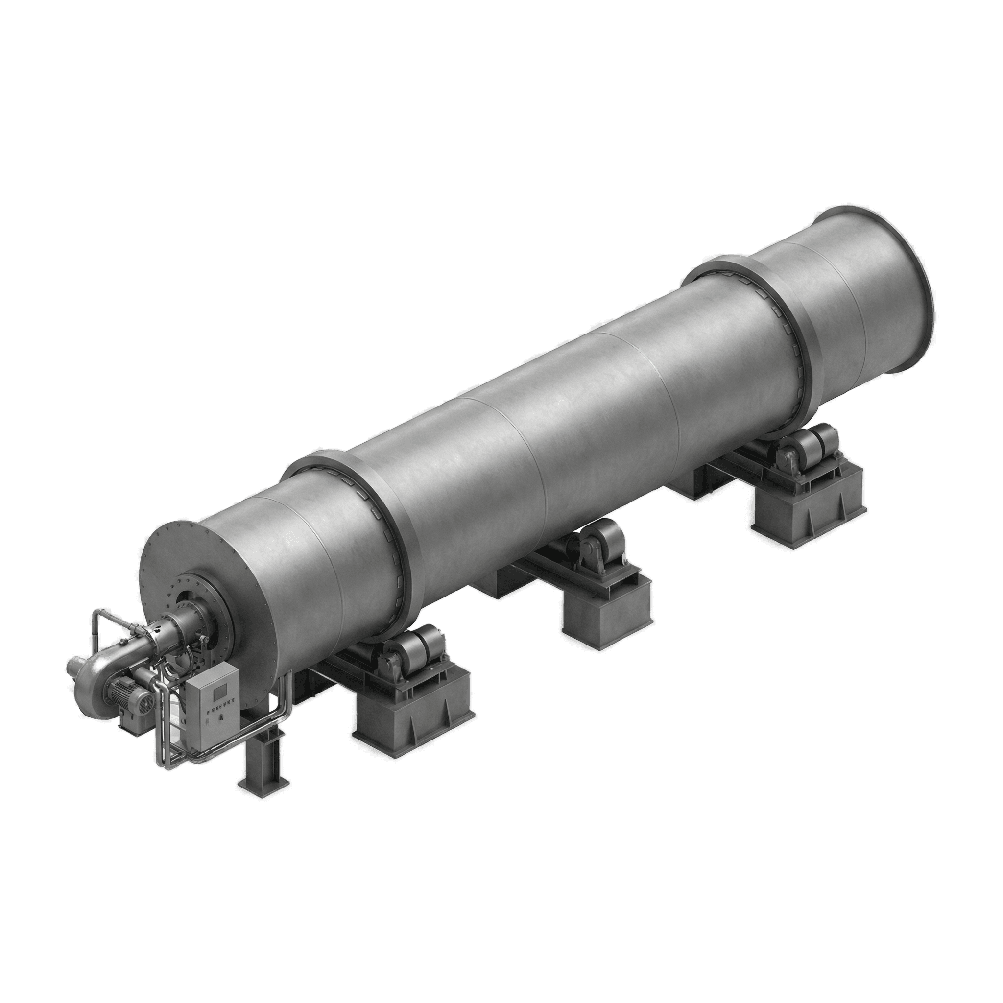
Kiln Inlet Chute Systems
Demander un devisAperçu
The kiln inlet represents one of the most sensitive transition zones in the pyroprocessing system.
At this interface, raw material enters a high-temperature rotary environment where combustion stability, calcination efficiency, and thermal distribution depend heavily on feed uniformity.
Any irregularity in material entry results in: flame profile distortion, uneven heat transfer, unstable material bed formation, increased fuel variability, and dust recirculation and build-up.
Kiln inlet chute systems must therefore function not only as structural components, but as process stabilization interfaces.
Oswal Engineers designs Kiln Inlet Chute Systems engineered to ensure controlled, uniform material introduction under high thermal and mechanical stress.
Engineering Objective
The primary function of the inlet chute is to guarantee:
Proper feed geometry directly influences combustion efficiency and clinker quality.
- Uniform material distribution across the kiln cross-section
- Controlled feed trajectory into the rotary shell
- Stable material curtain formation
- Minimal dust recirculation
Process Sensitivity at the Inlet
The inlet zone governs:
Irregular feed entry can lead to:
Precision inlet design supports thermal equilibrium.
- Flame stabilization
- Pre-calcination uniformity
- Gas-solid interaction
- Heat transfer efficiency
- Localized overheating
- Incomplete calcination
- Increased specific fuel consumption
- Refractory stress
Structural & Mechanical Design
Oswal kiln inlet chutes are engineered for:
Design calculations consider:
Fabrication tolerances are maintained to ensure alignment continuity and mechanical integrity.
- Reinforced structural fabrication
- High-load bearing capacity
- Dimensional stability under thermal stress
- Resistance to deformation
- Material impact forces
- Gas flow interaction
- Thermal expansion
- Structural fatigue under cyclic loading
Wear-Resistant Engineering
The inlet chute is continuously exposed to:
Oswal systems incorporate:
Wear management ensures extended service life and predictable maintenance intervals.
- Abrasive raw material
- High dust concentration
- Elevated temperature gradients
- Wear-resistant lining systems
- Replaceable abrasion plates
- High-temperature resistant internal surfaces
Optimized Material Flow Geometry
Material trajectory is engineered to:
Flow simulation and practical field experience inform geometry optimization for consistent process performance.
- Avoid dead zones
- Prevent build-up formation
- Minimize turbulence
- Ensure stable feed curtain formation
Thermal Expansion Accommodation
The inlet region experiences differential expansion between:
Oswal inlet chute systems incorporate:
Thermal adaptability prevents structural fatigue and leakage.
- Kiln shell
- Stationary duct structures
- Chute assembly
- Expansion interfaces
- Stress-relief structural design
- Flexible mounting provisions
Process & Energy Impact
Proper inlet geometry directly supports:
Mechanical precision translates into thermal performance gains.
- Stable combustion profile
- Consistent calcination
- Reduced fuel overcompensation
- Lower draft fluctuation
- Improved kiln availability
Integration with Sealing Systems
Kiln inlet chute systems operate in coordination with:
Integrated engineering ensures minimal air ingress and stable draft behavior.
- Inlet sealing assemblies
- Radial and axial compensation seals
- False air control systems
Operational Advantages
Oswal Kiln Inlet Chute Systems deliver:
Reliable feed introduction protects overall pyroprocessing performance.
- Uniform material entry
- Reduced dust recirculation
- Improved combustion stability
- Lower maintenance frequency
- Extended structural lifespan
- Enhanced energy efficiency
Lifecycle Reliability
Systems are engineered for:
Durability is designed to match real cement plant operating conditions.
- Long-term dimensional stability
- Modular wear component replacement
- Retrofit compatibility
- Minimal downtime during service

Prêt à discuter de vos besoins ?
Contactez notre équipe d’ingénierie pour une assistance technique spécifique à l’application.